


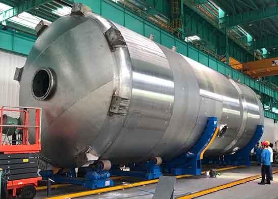
pressure vessels
Pressure vessels with external dimensions exceeding the transport limit must be transported to the construction site in sections or sections for assembly and welding.

Pressure vessels with external dimensions exceeding the transport limit must be transported to the construction site in sections or sections for assembly and welding.
Pressure vessels with external dimensions exceeding the transport limit must be transported to the construction site in sections or sections for assembly and welding. Due to the restriction of environment climate and construction conditions, the pressure and operating temperature of vessels are different, and the material and shell thicknesses for manufacturing pressure vessels are different. Especially for vessels requiring post-weld stress relief heat treatment, on-site construction conditions are poor, technical conditions are high, construction equipment and tools are numerous, and construction management is difficult.
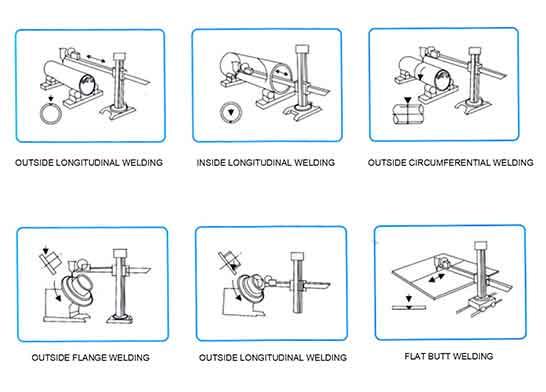 Welding positioner and welding manipulator are used together
As the parameters of pressure vessels vary greatly, and the specifications, materials and technical requirements vary greatly, it is difficult to prepare the on-site assembly welding. In addition to lifting equipment, welding equipment, preheating, post-heat exchanger, non-destructive testing equipment, heat treatment tooling, pressure test equipment, etc. are required and must be operated reliably. Some on-site work areas are small and, in addition to the different construction seasons, the climate in the north and the South varies greatly, so the construction difficulty is obvious.
In this paper, field assembly welding of pressure vessel is introduced with large diameter tower as an example.
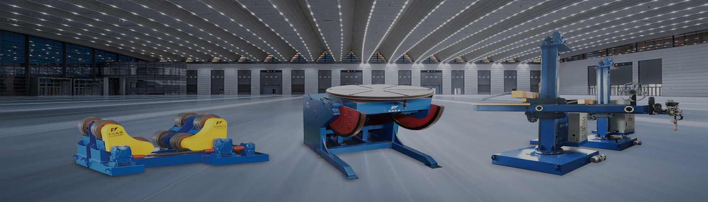
Welding auxiliary equipment for pressure vessel
Field assembly welding of large diameter tower
Field assembly welding of large diameter tower is the installation process of tower which is assembled and welded in the construction site due to transportation, construction conditions on site, lifting and other reasons and is processed into semi-finished products in the factory.
1. General Provisions
(1) Towers assembled and welded on site shall be assembled after the semi-finished products and parts have been accepted and accepted as required.
(2) The tower assembly shall be carried out according to the design drawings, layout and construction scheme. Each process shall have self-inspection and process handover records, and each control point shall have the signature and confirmation of relevant personnel of quality system.
(3) The following procedures shall be adopted for on-site assembly welding of tower: assembly welding of upper and lower heads on steel platform single barrel body combination welding of single section and head combination welding between single section combination welding of skirt and lower head section assembly welding into large sections welding each section in sequence into a whole. If construction conditions permit, the semi-finished products shall be assembled and welded in the factory as far as possible to reduce the on-site assembly welding workload.
(4) When assembling the barrel joint of the composite steel plate, take the multi-layer as the basis to prevent over-standard staggered edges and influence the quality of the multi-layer welding. Locating plate and group pair clamps shall be welded to the base side to prevent damage to the base.
(5) Segmental or integral lifting of tower shall comply with relevant regulations.
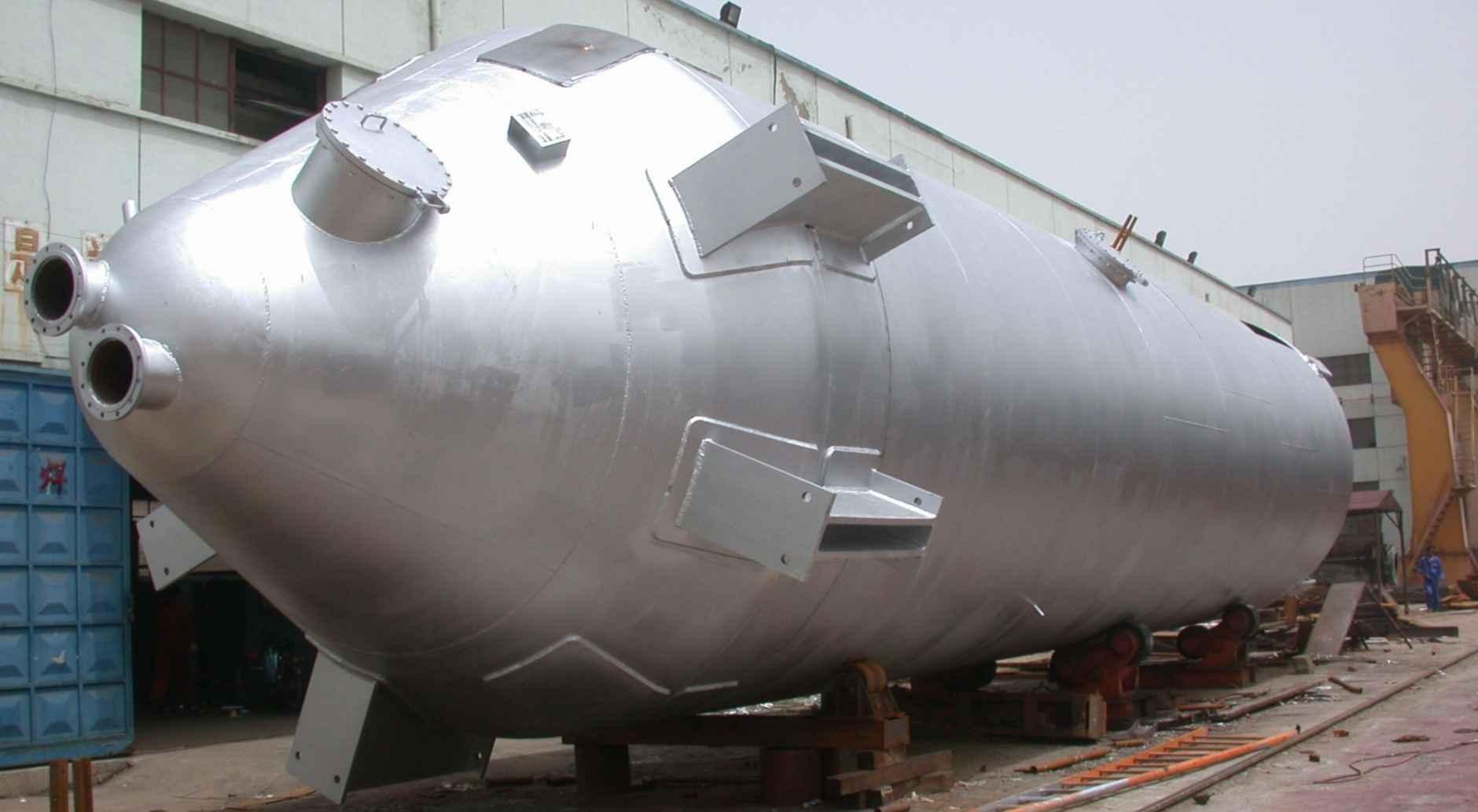 Storage pressure vessel
2. Assembly of cylinder and head
(1) The spherical head shall be assembled according to the following procedure
A. Draw assembly datum circle on the steel platform. The diameter DB of the datum circle of the head can be determined as follows:
DB=Di+n × G/pi
G-contra clearance in the formula, generally 2mm; N - Number of head lobes.
B. Spot-weld the locating plates at the distance of 100mm from the equal line by dividing the reference circle into equal parts according to the number of flaps n of the head, and no less than 2 locating plates for each flap.
C. In the assembly datum circle, set the head assembly tire, take the positioning plate and the assembly tire as the datum, use the tool card to make the disc close to the positioning plate and the tire, and adjust the gap between the counterparts and the amount of staggered edges.
(2) The assembly of each weld shall be inspected and recorded after the steel platform group has completed the head. It is necessary to check the gap, wrong edge, edge angle, roundness, etc. After all groups of heads have been aligned and checked to meet the requirements and recorded well, 2-4 arc reinforcement plates can be added to each longitudinal joint to reduce welding deformation according to the length and plate thickness of the joint. After re-inspection, the procedure shall be handed over to the next procedure for welding.
(3) After the head is welded and inspected to be qualified, four azimuthal buses (0?, 90?, 180?, 270?) are determined and marked according to the layout, and the pipes are welded according to the opening azimuth diagram.
(4) When the single cylinder body is assembled, the reference circle of the cylinder body should be drawn on the steel platform according to the number of plates per circle N and the actual circumference of the end of the head. Weld a positioning block about 500 mm on each side of the base circle.
(5) When single-section cylinder body is assembled, the plates of the same circle are lifted to the reference circle on the steel platform one by one in sequence according to the layout and matched with special tools.
(6) After the single cylinder body is assembled on the steel platform, the welding seam assembly is checked and recorded. To counter clearance,
Check the amount of offset edges, the angle of edge formed in the ring direction, roundness, circumference difference between adjacent cylinders, end surface roughness and height.
(7) After the single cylinder body has been qualified, go through the procedure transfer procedure and submit it to the next procedure for welding.
(8) For cylinders and heads with large diameter and poor rigidity, temporary reinforcement measures with the shape of "10" or "m" should be taken according to specific conditions. The reinforcement should be supported on the circular arc reinforcement plate.
(9) After the welding of a single cylinder body is completed and the welds pass the NDT, the shape inspection after welding shall be carried out and the records shall be made after the inspection as the original record of the single-section combination welding.
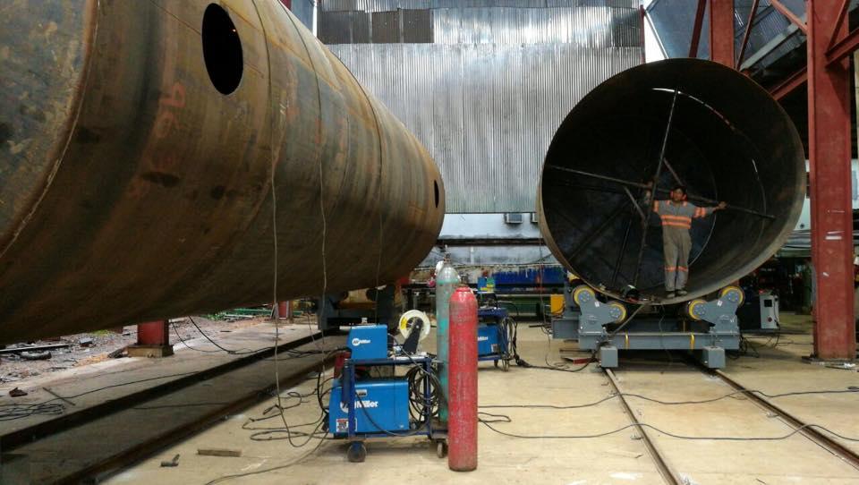
Use welding rotator for welding
3. Welding of cylinder and head
(1) Welding construction shall be carried out strictly in accordance with welding procedure.
(2) Vessel welding shall adopt the following procedure to weld large groove side of upper and lower head weld on platform small groove side after root clearing non-destructive testing large groove side of longitudinal weld of single cylinder body small groove side after root clearing non-destructive testing welding on roller frame; Lower head and single cylinder circumferential weld large groove side root clearing rear weld small groove side NDT welded lower head cylinder and skirt fillet weld weld appearance inspection Welded Large Section circumferential weld large groove side root clearing rear weld small groove side NDT welded joint welded vessel inner fixture and outer reinforcement ring welded sectional fixture large groove side root clearing Small groove side of rear welding NDT.
(3) When welding composite plate vessels, the groove on one side of the base shall be welded first, and then the side of the composite plate shall be welded after root clearing.
(4) In order to reduce welding deformation and residual stress, the sectional back-welding method should be adopted for the bottom pass of long weld.
(5) Arc initiation shall be in groove, arc initiation shall be by backwelding method, arc pits shall be filled when arc extinguishing, and the layers and indirect ends of multi-layer weld beads shall be staggered.
(6) For double butt welds, backside root cleaning should be carried out after one side welding. Carbon arc gouging, grinding wheel or other mechanical grinding methods can be used for root cleaning of welds. After carbon arc air gouging, grinding wheel should be used to trim the groove, remove the carburized layer, copper spots, etc. When removing the root of weld, the deposited metal of positioning weld should be removed. The groove shape after root cleaning should be uniform in width and narrowness. No root cleaning is required when cushion is used on the back of butt weld.


